

Hot mirrors vs cold mirrors: What’s the difference and when should you use each?
“Hot mirror”, “cold mirror”, and “IR-cut filter” are used interchangeably more often than they should be. Understanding the distinction is the first step towards specifying the correct component.
Understanding the differences
All three are designed to separate visible light from infrared radiation. They differ in the precision of the spectral transition and the way unwanted wavelengths are managed.
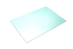 |
IR-cut filters transmit visible light (roughly 400–700 nm) and block or reflect near-infrared, with a sharp, precise spectral transition. They’re built for precision imaging applications where colour accuracy matters. The goal is to stop any stray near-infrared light reaching the sensor, because even a small amount will skew colour reproduction. In imaging systems, IR-cut filters often perform a similar function to hot mirrors by transmitting visible light while rejecting near-infrared wavelengths. However, they are typically specified with much tighter spectral requirements to preserve colour accuracy. |
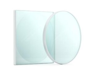 |
Hot mirrors reflect infrared away while transmitting visible light. The emphasis here is thermal management. They protect downstream components from heat build-up, rather than achieving a razor-sharp spectral cut-off. A hot mirror is primarily designed to reduce thermal load by reflecting infrared energy away from the optical path. While some designs feature sharp spectral transitions, colour accuracy is usually not the primary performance requirement. |
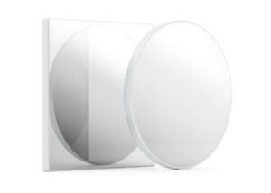 |
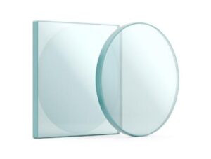
Cold mirrors are the functional opposite: they reflect visible light and transmit infrared. They’re used to redirect visible light within an optical path while letting the heat-carrying infrared energy pass straight through, rather than reflecting it back into the system. |
 |
A fourth option that often gets overlooked is heat-absorbing glass filters (such as Schott KG1). Rather than reflecting or transmitting selectively via a coating, these absorb NIR/IR light directly. They provide a cost-effective solution for managing heat in simpler systems, but because the energy is absorbed rather than redirected, thermal load can build up in the glass itself. This makes them unsuitable for high-intensity or high-power systems where that absorbed heat has nowhere to go. |
The optical principle behind the coatings
Mechanically, hot mirrors, cold mirrors, and IR-cut filters all rely on the same underlying principle: multi-layer dielectric thin-film coatings, often only tens of nanometres per layer, that use optical interference to control what’s transmitted and what’s reflected. Some wavelengths are cancelled out through destructive interference; others are reinforced through constructive interference. Adjusting the number, thickness, and arrangement of these layers is what determines exactly where the spectral cut-off sits and how sharp it is.
Can hot and cold mirrors be swapped?
Functionally, yes. The choice of which one to specify comes down to where the detector sits in the optical path and whether you want to redirect visible light or infrared. Swap the position of the detector and the heat path, and you can often swap the mirror type and reach an equivalent result.
In practice, though, most systems are designed around one or the other, chosen to suit the optical path layout, rather than using both simultaneously. Retrofitting a cold mirror into a system designed around a hot mirror, or vice versa, often requires more redesign effort than anticipated.
How to decide which one you need depends on the application and system requirements:
- An IR-cut filter is best suited to applications requiring a precise, sharp spectral cut-off for imaging accuracy.
- A hot mirror prioritises thermal management, where the exact sharpness of the spectral transition is less critical.
- A cold mirror reflects visible light while transmitting infrared radiation, allowing heat to pass through the system.
A heat-absorbing glass filter (KG1) is a suitable option for simpler, cost-sensitive systems that do not operate at high light intensities.
Where each type gets used
- Defence HUDs rely on IR-cut filters to keep symbology clear and free of colour distortion from stray infrared.
- Subsea imaging systems often use IR-cut filters and colour-correction filters to compensate for wavelength-dependent light absorption in water.
- CCTV, general imaging, and microscopy applications commonly use all three filter types, depending on the specific optical layout and whether thermal management or colour accuracy is the priority.
When the substrate provides the filtering function
Certain substrate materials filter light without any coating at all. Standard fused silica transmits UV light well, while UV-grade fused silica offers improved transmission at shorter ultraviolet wavelengths.
Silicon is opaque to visible light and begins transmitting in the near-infrared at approximately 1.1-1.2 μm, making it useful as an intrinsic visible-blocking filter.
This is a useful point for procurement teams to consider: the right material choice can sometimes remove the need for additional coating altogether, which has a direct impact on cost and lead time.
Key specifications to get right
- Transmission and reflection ranges, substrate material, and refractive index. Coating design has to change depending on the refractive index of the substrate, so the two can’t be specified in isolation.
- Angle of incidence (AOI). A filter designed for one angle will behave differently at another. It’s a detail that’s easy to overlook and hard to miss once it’s wrong: A cold mirror designed for a specific angle may behave very differently when tilted, as the reflected and transmitted spectral bands shift with angle of incidence.
- Polarisation sensitivity. This becomes increasingly significant at higher angles of incidence, particularly in systems using polarised light sources.
- Coating type and deposition method. Standard deposition methods suit most applications, but for high-power or laser systems, ion beam sputtering (IBS) is often specified by name. It’s generally more durable and better suited to demanding environments, at a higher cost than standard deposition.
Environmental durability, matched to where the filter will operate. Temperature range, humidity, and mechanical exposure all matter here.
Getting the specification wrong can mean colour distortion, reduced measurement accuracy, or false readings if unwanted wavelengths reach the detector. In more severe cases, particularly high-power or laser systems, it can mean sensor damage from unfiltered radiation reaching components that were never designed to handle it.
- Not specifying angle of incidence, then being surprised when real-world performance doesn’t match the datasheet.
- Overlooking polarisation sensitivity in systems using polarised light.
- Choosing standard-deposition coatings for high-power or laser applications, where the added durability of IBS coatings is required.
Specifying the right filter
Hot mirrors, cold mirrors, IR-cut filters, and heat-absorbing glass filters all solve a version of the same problem, but they’re not interchangeable, and the details – angle of incidence, polarisation, coating deposition method, substrate – determine whether a filter performs as expected in your system or falls short.
Knight Optical can provide all three filter types, as well as heat-absorbing glass filters. If you’re weighing up which filter type fits your system, get in touch with our technical sales team to talk through your specification.