
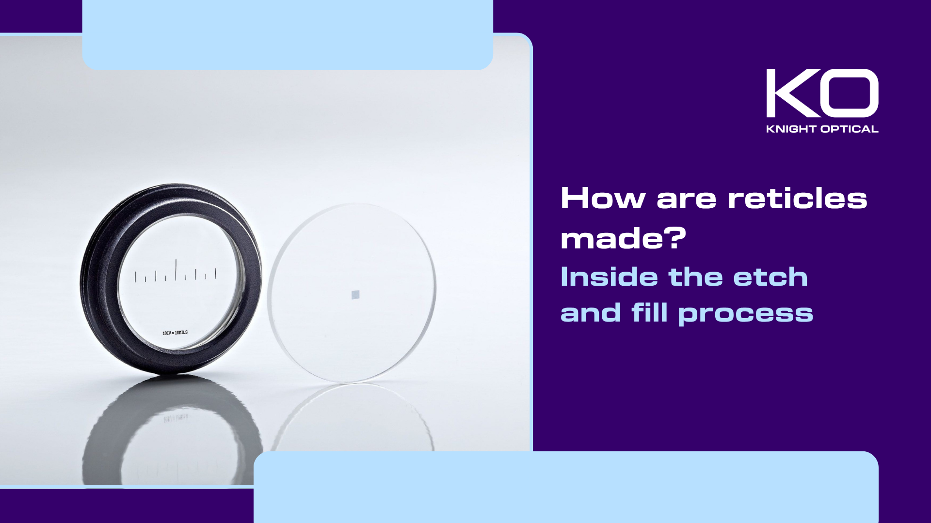
How are reticles made?
Inside the etch and fill process


Two reticles with the same nominal pattern and substrate material may still perform differently if etch depth, fill quality, line edge quality, feature placement and substrate flatness are not controlled to the same limits. These factors are determined by the manufacturing process and may not be fully defined by the pattern artwork alone.
Reticles are used in microscopy, metrology, optical sights, alignment instruments and inspection equipment, and can be manufactured using several different processes. This article follows the etch and fill process from substrate selection through to final inspection, explaining how accuracy is controlled at each stage.
Step 1: selecting the substrate
Knight Optical produces etch and fill reticles on B270 and N-BK7, including on windows and prisms. Both are crown glasses with good visible transmission and a well-characterised refractive index, and both etch predictably in a hydrofluoric-based bath.
The choice between them depends on the optical, mechanical and cost requirements of the application. N-BK7 is a borosilicate crown glass available with tightly controlled optical properties, while B270 is a more economical crown glass suited to many reticle applications. Homogeneity, inclusion content, transmission, thickness and dimensional tolerances should all be considered when selecting the substrate.
Flatness and wedge are particularly important when the reticle is positioned at or near an image plane.
Because the reticle is a transmissive optical element, surface form, thickness variation and material homogeneity can contribute to transmitted wavefront error. The effect on the instrument depends on the reticle’s position and the optical design but may include local image displacement or changes in focus across the field.
Wedge displaces the image. For small wedge angles, the angular deviation is approximately equal to the refractive index minus one, multiplied by the wedge angle.
Surface quality is also important. When the reticle is located at or near an image plane, scratches, digs or contamination may be visible in the image and could be mistaken for pattern features.
Step 2: photolithography and defining the pattern
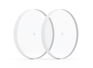
The pattern begins as high-resolution artwork that is transferred to a master, typically produced in chrome on glass. Creating the master introduces an initial tooling cost, but the same master can be used across a production run. This generally reduces the cost per component as batch quantities increase.
The substrate is cleaned and coated with photoresist. If spin coating is used, the resulting film thickness is influenced by factors including resist viscosity and spin speed. Variations in resist thickness can affect exposure and development behaviour, contributing to variation in the finished line width.
After a soft bake to remove solvent, the resist is exposed using the master. In contact or proximity printing, the separation between the master and the resist affects image definition. A larger gap increases diffraction at the feature edges and can limit the minimum line width that the process can reproduce reliably.
Development removes either the exposed or unexposed resist, depending on whether a positive or negative resist is used, leaving a patterned resist layer on the glass. A subsequent bake may be used to improve adhesion and chemical resistance before etching.
Step 3: chemical etching
The exposed glass is etched in a hydrofluoric-based solution, transferring the resist pattern into the substrate itself.
Wet etching of glass is generally isotropic. The etchant removes material laterally beneath the resist as well as vertically into the substrate. The resulting undercut may be comparable with the etch depth, although the exact relationship depends on the glass, mask and process conditions. This places a practical limit on the combination of groove depth and minimum line width that can be achieved.
Etch depth and finished line width are therefore closely related. Etch depth is influenced by factors including bath concentration, temperature, agitation and process time. As the condition of the bath can change during use, maintaining consistent results requires the etch rate and other process variables to be controlled.
Groove depth affects the amount of pigment that the feature can hold and can therefore influence the contrast or optical density of the finished line. Pigment formulation, fill quality, curing and illumination conditions also affect the observed result.
Step 4: holding micron-level accuracy
Knight Optical produces etch and fill reticles with line widths from 5 µm to 500 µm on substrates measuring from 10 mm to 100 mm.
At the fine end of this range, variations in resist thickness, exposure, development, mask contact and etch conditions can all affect the final line width. Maintaining micron-level dimensional tolerances therefore requires a controlled process and a defined error budget rather than relying on the nominal resolution of the master alone.
Feature placement and line width should be specified separately. Nominal feature placement is established by the master artwork and its registration to the substrate, although etch bias and non-uniform undercut can affect the final position of the feature edges. Placement accuracy is particularly important for patterns containing an absolute scale, such as measuring graticules, because positional errors introduce corresponding measurement errors.
Batch repeatability depends on controlling resist coating, exposure, development, registration, etching and pigment filling within established process limits.
Step 5: pigment fill
The etched grooves are filled with pigment in red, black or white, and the excess is removed so the fill sits flush with the surface. Pigment colour affects the contrast and illumination method of the finished reticle.
 Black pigment absorbs incident light, producing dark pattern features when the reticle is viewed in transmission against a bright field. This arrangement is commonly used in daylight or other well-illuminated conditions.
White pigment scatters light. In an edge-illuminated reticle, light is coupled into the substrate and guided towards the etched features, where the pigment scatters it towards the observer. This produces a bright pattern against a darker background and allows the reticle to be used under low-light conditions.
Red pigment provides a coloured pattern that may offer greater contrast than black against certain backgrounds. It can also be used in illuminated reticles designed for low-light viewing, subject to the illumination wavelength and system requirements.
Groove depth affects the volume of pigment within each feature and can influence the contrast of black-filled lines and the scattering performance of white-filled lines. Pigment formulation, fill consistency, curing and illumination also contribute to the final appearance. Groove geometry and visibility requirements should therefore be considered together when specifying the reticle.
Quality assurance and compliance
Pattern dimensions and feature positions are verified using a Starrett video measurement system. The non-contact system can measure line widths, distances, angles and other pattern features across parts up to 300 mm. Programmable measurement routines allow the same inspection sequence to be applied across a production batch.
Flatness, surface irregularity and transmitted wavefront error can be measured using a Zygo Verifire XPZ phase-shifting Fizeau interferometer. For a reticle used in transmission, transmitted wavefront testing can show the combined effect of surface form, thickness variation and material homogeneity on the emerging wavefront.
Visual inspection is carried out against the applicable drawing requirements. These may reference ISO 10110 or MIL-PRF-13830B, depending on the application. Knight Optical can assess surface quality requirements down to 10/5 scratch and dig.
Manufacturing is carried out within Torrent Photonics’ ITAR-registered facilities. Inspection to applicable military specifications is available where required by the drawing or customer specification.
From prototype to production
 Photolithography requires an initial investment in the master artwork and process setup. Once the master has been produced, its cost can be distributed across the production quantity, reducing the tooling cost per component as volumes increase.
Using the same master across a production run supports consistent nominal pattern geometry. Batch-to-batch repeatability also depends on controlling the subsequent coating, exposure, development, etching and pigment-filling processes.
Repeatability is particularly important for programmes with a long service life. A replacement reticle produced several years after the original batch may need to match the original pattern geometry and optical specifications closely enough to minimise changes to the instrument’s alignment or calibration.
How manufacturing affects reticle performance
Reticle performance depends on more than the nominal pattern geometry and substrate material. Etch depth, pigment fill, line edge quality, feature placement, wedge, surface quality and flatness may all affect performance. Where these properties are critical to the application, they should be defined on the drawing or agreed as part of the technical specification.
Knight Optical manufactures etch and fill reticles on B270 and N-BK7, including patterns applied to windows and prisms, with line widths from 5 µm to 500 µm.
Components are inspected in-house against the applicable drawing requirements.
To discuss your pattern, substrate and inspection requirements, contact our technical sales team.